GrabCAD - Alstom Challenge Submission

March 25, 2018 0 Comments

Hi everyone!

As promised I will make a post regarding Creating Machines submission on Alstom Engineering challenge promoted by GrabCAD !
This is the last day for ideas submission and a lot of cool stuff is already submitted!
So, lets start explaining the main objective of the contest. The objective is to reduce the weight and the manufacturing cost of the CVS and battery box support that already exists on Metropolis City Train. You need to accomplish the Norms given (challenge´s attached documentation) and use only the available volume (restricted volume also in the attached documentation).

Now lets go to my idea. 

This structural support is a welding construction based on the design of some building and bridge structures and on some aircraft structures as well.
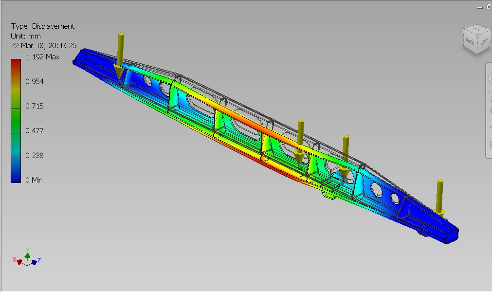
Every component is made of laser cutting sheet metal parts. 
The material can be normal S235JR Steel but for more resistance other materials can be used, for example S275J2G3 or S355J2G3 (1.0570). 


The thickness of the main body is 6mm. Lower the thickness of the main body can surely be possible and lower the total weight can be achieved, but I really think that a total weight of 28,8kg is way better when compared to the actual support weight (56,5kg). 

A complete set has a total of 144 kg (Alstom´s actual set has 282,5kg), there is no need to change the bolt joint support on the train solebar and it fits perfectly on the available volume. 


The welded construction can take more time but on the other hand, combined with folded sheet metal steel makes it more stable and reliable. With some changes on the design it can also be used riveted connections like it is used on bridges and skyscraper construction or even on aircraft Industry.

The design accomplishes the standard Norms (EN12663; EN61373; Alstom Standard ENG-STD-003; EN 45545-2).


Unfortunately, due to lack of time is impossible to present more variations to this design, but I’m extremely happy with this design in particular and with the overall result and I really believe that this structure is something that can be putted on practice and has a realistic vision on which design, safety and overall feasibility is concerned.

For more detailed information about the contest and to see other submissions go to: https://grabcad.com/challenges/redesign-the-structural-support-of-the-metropolis-metro-underframe


All 3D files are available for download here on Creating Machines, just go to the Downloads field on the very top of the Blog. 


0 comentários:

Alstom launches an engineering challenge on GrabCAD

March 12, 2018 1 Comments

GrabCAD Community Website has launched together with Alstom partnership, a contest to develop a new structural battery support for a city train ( Metropolis Metro ). 
Anyone that is registered on GradCAD can participate. 
Just need to follow all the rules, come up with a new solution and present it along with 3D files, some fotos and a text explaining what advantages does the solution bring. 


Note : You can submit more than one solution  during the contest. 

The deadline is March 26th, 2018. 
The prizes are :

1st place -    6.000$ 
2nd place -   4000$
3rd place -   2000$

For more informations and 3D files visit : 

Creating Machines is going to submit a solution as well and I will share it with you on my next post. 

Submit yours too!! What are you waiting for?? 
" Think Mcfly!! Think!! "

1 comentários:

Design for Manufacturing and Assembly (DFMA)- Part two

March 11, 2018 1 Comments

Design for Manufacturing and Assembly ( DFMA ) -  Guidelines


1. Reduce the Part Counts:


· Design engineers should try for product design that uses the minimum number 
of parts. 


· Fewer parts result in lower costs. 


· It also makes assembly simpler and fewer chances of defects. 


· Minimize part count by incorporating multiple functions into single parts.


One method for determining minimum part quantities is to first list out all the components in your assembly, including hardware. Then ask the following questions:


Can the part be manufactured using the same material as other parts?

How does the part in question move in relation to other moving parts?

Can the parts be combined without need for any special process or tooling?

If combined with another part how does that impact ease of possible disassembly?

If combined with other parts how would it impact ease of manufacture?


Through reduction of component part quantities, you also reduce the amount of hardware and the number of assembly steps required. The likelihood of assembly errors are subsequently reduced in relation to the reduction in assembly steps.


2. Use modular designs:


Modular design is becoming more prevalent in many industries. It has various advantages for the manufacturer, the dealer and the customers. Some of the advantages to modular design are listed below:


· Modularize multiple parts into single sub-assemblies. 


· Modular design reduces the number of parts being assembled at any one time 
and also simplifies final assembly. 


· Field service becomes simple, fast and cheap because dismantling is faster and 
requires fewer tools. 


· Modules help minimize cost by reducing the number of different parts within a family of products

· Modules may result in shorter learning curves when new employees require training on the assembly of the products

· In some cases, it allows the manufacturer to balance production throughout the year based on projected seasonal sales

· In addition, the dealer can stock most sold items for fast delivery to customer. Customized combinations of the modules can be delivered to the site and installed quickly.

· Modules allow for greater outsourcing of parts and assembly modules, freeing-up manufacturing capacity and increasing the number of products delivered on time

· Modules provide for easy and quick installation of products at the site saving labor and time

· Modular assemblies can also be improved with minimal effect on the rest of the product


3. Assemble in the open:


· Design to allow assembly in open spaces, not confined spaces. 


· Assembly operation should be carried out in clear view. This is important in 
manual assembly. 


· Always allow for adequate tool clearance and assure the operator can see what they are assembling, with no hidden interfaces or attachment points.


4.Optimize part handling:


· Design parts so they do not tangle or stick to each other or require special

handling prior to assembly.


5. Do not fight gravity:


· Design products so that they can be assembled from the bottom to top along 
vertical axis. 


· Design the first part large and wide to be stable and then assemble the smaller 
parts on top of it sequentially. 


6. Design for part identity (symmetry):


· Symmetric parts are easy to assemble. 


· Maximizing part symmetry will make orientation unnecessary. 


· Features should be added to enhance symmetry wherever required. 


7. Eliminate Fasteners:


Threaded bolts, washers and nuts are time consuming to assemble. If they are required, consider weld nuts or nuts that are captured in the part. The designer must look at alternative methods of attachment.

Minimize the variety of hardware required for assembly


· Fasteners are a major obstacle to efficient assembly and should be avoided 
wherever possible. 


· They are difficult to handle and can cause jamming, if defective. 


· If the use of fasteners cannot be avoided, limit the number of different types of 
fasteners used. 


· Consider the use of connections integrated into the parts such as snap fit or tab and slot

· Evaluate other bonding techniques with adhesives

· Match fastening techniques to materials and product functional requirements

· Consider ease of disassembly for service and repairs


8. Design parts for simple assembly:


There are many methods to design for ease of assembly. When designing for assembly, remember the simpler the design the easier it is to assemble. The designer should consider where the assembly is going to be performed and the tools or equipment that will be available. For example, if the product is sold as a kit and assembled in the field by the customer, it is different than if it will be assembled on an assembly line or in a work cell. There are many guidelines for ease of assembly. The following list contains some examples:

· Incorporate simple patterns of movement in your assembly process and minimize steps. If that is not possible, consider breaking it down into logical sub-assemblies.

· Avoid multiple set-ups or re-orientation during the assembly process. This creates wasted movement and time.

· Parts should incorporate lead-in features and chamfers. This allows for easier insertion of pins or bolts.


9. Parts should easily indicate orientation for insertion:


· Parts should have self-locking features so that the precise alignment during assembly is not required or provide marks (color) to make orientation easier.


The design engineer should consider how the parts are going to be handled and oriented during the manufacturing and assembly processes. If this is not done, the impact could range from non-value-added motion and part movement to possible operator safety issues or requirements for special fixtures or lifting devices. There are several basic principles that can be applied to improve parts handling and orientation. A few examples can be found below:

· Drawings should consistently indicate the proper origination when fed into a process. An example would be how parts are oriented into a brake press for either bend up or bend down operations.

· The designer should avoid use of parts that can easily become tangled in the container or that are difficult to pick up and handle. This slows production and can increase waste due to damaged, dropped or lost parts.

· When possible, design parts that are symmetrical along both axis. This allows for ease of fabrication and correct assembly.

· Parts should be designed so that they may be easily grasped, oriented and placed in an assembly or weld fixture. Examples would be parts with flat, parallel surfaces that are easily picked-up and assembled by the operator. Another instance to think about could be if the part is picked up by a suction or magnetic gripping device when used in a “pick and place robot” application.

· Always avoid parts with sharp edges, burrs or points. Use radii and chamfers when possible to reduce chance of operator injury.

· Avoid heavy or oversized parts that will require lifting devices or may increase worker fatigue and risk of injury. Always consider assembler and operator safety in all designs.

· When designing a workstation, it is good practice to plan for minimum worker travel time. Minimize the distance to access and move a part or assembly. A good rule of thumb is that most components should be within two steps from the point of assembly and common hardware and tools within easy reach.


10. Standardize parts to reduce variety:


· Using the same commodity items such as fasteners can avoid errors. 


· It also reduces the cost. 


11. Color code parts that are different but shaped similarly:


· Distinguish different parts that are shaped similarly by non-geometric means, such as color coding.


12. Design the mating features for easy insertion:


· Add chamfers or other features to make parts easier to insert.


13. Provide alignment features:


· Design parts with orienting features to make alignment easier.


14. Place fasteners away from obstructions:


· It is better to locate fasteners in place where one has access to the fastener.


15. Deep channels should be sufficiently wide to provide access to fastening tools:


16. Provide flats for uniform fastening and fastening ease:


· Do not fasten against angled surfaces.


17. Design Parts for Ease of Fabrication


The designer should consider the method of fabrication that may be used for producing the parts, the required material specifications and required production volumes. Some particular guidelines to review are as follows:

· Specify materials that are commonly used and compatible with existing production processes that will minimize processing time and will meet all functional requirements

· Review the part and eliminate unnecessary features that could result in additional process steps, extra effort and complex or expensive tooling

· Design reviews with members of process engineering, quality control and the fabrication team are beneficial when possible. In most cases the meetings result in a few changes to the design that increase utilization of existing tools or improve machine utilization, preventing the need for capital expenses for special tools. In addition, the meetings improve knowledge transfer of design intent to all levels of the organization.


18. Design for Automated Production


There are many obvious advantages to designing products or parts for automation. A few of them are listed below:

· Increased process throughput or efficiency.

· Improved quality or more predictable process results.

· Consistency in the process output.

· Reduced operator labor costs and indirect labor costs


Something else to consider is the fact that automated production can require less flexibility in design than manual production. The product must be designed so that it can be handled with automated equipment like gripping or magnetic lifting and placement equipment. Avoid any requirements for gripper / tool change. You must also use self-locating parts, simple parts-presentation devices and avoid the need for clamping or securing parts during assembly or processing.


Design for Manufacturing and Design for Assembly are both important and often interwoven and referred to simply as DFMA. The primary goal is to design a product and process to be as efficient as possible. Whether a product is assembled by machines or by operators, the designer and the mechanical engineer should work together to ensure that labor cost, overhead and materials are reduced as much as possible. We should always strive to produce a quality product the first time and every time and Design for Manufacturing and Assembly can help! When DFMA is applied, your company can run at higher profit margins, with higher quality and at a greater level of efficiency.

1 comentários:

Design for Manufacturing and Assembly (DFMA) - Part one

March 10, 2018 2 Comments


DFMA is a combination of two methodologies, Design for Manufacturing (DFM) and Design for Assembly (DFA). DFM is the method of design for ease of manufacturing of the collection of parts that will form the product after assembly and DFA is the method of design of the product for ease of assembly. This combination enables a product design to be efficiently manufactured and easily assembled with minimum labor cost.


DFA focuses on the optimization of the part/system assembly 


DFA is a tool used to assist the design teams in the design of products that will transition to production at a minimum cost, focusing on the number of parts, handling and ease of assembly. 


Concerned only with reducing product assembly cost 
  • Minimizes number of assembly operations
  • Individual parts tend to be more complex in design 


DFM focuses on optimization of the manufacturing process. 


DFM is a tool used to select the most cost-effective material and 
process to be used in production in the early stages of product design. 


Concerned with reducing overall part production cost 
  • Minimizes complexity of manufacturing operations 
  • Uses common datum features and primary axes 
 

Fig.1 - Design before DFMA optimization

Fig.2 - Design after DFMA optimization
  
The DFMA methodology allows for new or improved products to be designed, manufactured and offered to the consumer in a shorter amount of time.  DFMA helps eliminate multiple revisions and design changes that cause program delays and increased cost. With DFMA the design is often more comprehensive, efficient to produce and meets the customer requirements the first time.  A shorter total time to market frequently results in lower development costs.  The application of the DFMA method results in shorter assembly time, lower assembly cost, elimination of process waste and increased product reliability.


        Fig.3 - Design before DFMA optimization                  Fig.4 - Design after DFMA optimization


Many companies today are integrating the DFM and DFA practices through design and manufacturing teamwork. The Design for Manufacturing (DFM) and Design for Assembly (DFA) techniques are two different classifications. DFM techniques are focused on individual parts and components with a goal of reducing or eliminating expensive, complex or unnecessary features which would make them difficult to manufacture. DFA techniques focus on reduction and standardization of parts, sub-assemblies and assemblies. The goal is reduce the assembly time and cost. But if you think about it, they must be integrated to prevent one from causing negative effects on the other. The designer may seek to combine parts to reduce assembly steps, quantity of parts and hardware. If the resulting parts are difficult or expensive to manufacture then you have gained nothing. We must work together to accomplish both goals. The principle goals for simultaneous DFM/A are detailed in the next Post - Design for Manufacturing and Assembly (DFMA) - Part two.


2 comentários: